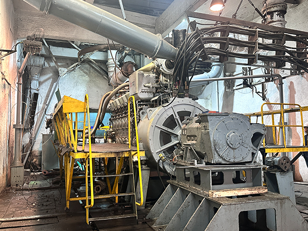
An engine is only as reliable as its fuel delivery system. Liquefied petroleum gas presents unique phase-change challenges for power generation. During high-load operations or cold ambient conditions, the natural vaporization rate of the fuel drops rapidly. Tank pressure plummets, often falling below the critical 11 water column inches or required bar thresholds. When this happens, the engine experiences severe fuel starvation. You face unstable power output or complete system failure.
Relying on passive vapor withdrawal is a common mistake in large-scale projects. You must transition to engineered fuel trains. Active liquid withdrawal and vaporization serve as the definitive method for ensuring reliability in commercial and industrial applications. We will break down the thermodynamic realities of vapor pressure. You will learn how to engineer a robust fuel delivery system. This approach prevents vapor lock, eliminates lean running conditions, and guarantees continuous operation regardless of ambient temperature drops.
Key Takeaways
Physics Dictate Performance: High draw rates cause rapid temperature drops inside the tank (auto-refrigeration), making passive vapor withdrawal unviable for continuous, high-kW industrial loads.
Liquid Withdrawal is Mandatory for Scale: Reliable industrial power generation systems require liquid withdrawal paired with dedicated vaporizers to ensure consistent fuel pressure regardless of ambient temperature.
Component Sizing is Critical: An underpowered LPG reducer or improperly sized vaporizer will bottleneck the system, restricting the engine from receiving fuel at the required 0.9–1.8 bar pressure range and risking severe engine damage.
Vendor Engineering Matters: Selecting a gas generator set manufacturer that engineers the entire fuel train (tank-to-engine) mitigates the risk of vapor lock and compliance failures.
The Physics of Vapor Pressure in an LPG Generator Set
You must define the baseline success metric for any gas power project. The system must maintain a stable fuel supply pressure under a 100% block load. It must achieve this in the lowest historical ambient temperature of the site. If the pressure drops below the engine's minimum requirement, the system fails. Understanding the thermodynamics of phase change is non-negotiable for system designers.
Auto-Refrigeration and Tank Freezing
Pulling vapor directly from a storage tank initiates a phase change. The liquid fuel must boil to replace the extracted vapor. Boiling requires latent heat. One gallon of propane requires approximately 785 BTUs of heat to vaporize. The liquid extracts this heat from its own mass and the surrounding tank walls. This process rapidly lowers the temperature of the remaining liquid. We call this auto-refrigeration.
As the liquid temperature drops, the vapor pressure inside the tank falls proportionally. High fuel consumption rates accelerate this temperature drop. If the tank's wetted surface area cannot absorb enough ambient heat to replace the latent heat lost to vaporization, the system enters a death spiral. Eventually, the tank exterior drops below the ambient dew point. Condensation forms on the steel. In severe cases, atmospheric moisture freezes on the tank walls. This layer of ice acts as insulation. It prevents ambient heat from warming the liquid inside. The vaporization process stalls entirely. The tank pressure collapses, and the engine starves.
Consider a 500kW generator pulling from a 1,000-gallon tank at 20°F. If you rely on passive vapor withdrawal, the tank will freeze solid in under four hours. The physical surface area of the steel simply cannot transfer enough BTUs from the cold air to sustain the required boiling rate.
Fuel Composition Variables
The specific mixture of your fuel heavily dictates baseline vapor pressure. Gas suppliers blend different hydrocarbons based on regional climates. You must understand how these blends affect your LPG generator set.
Propane (HD-5): Pure propane vaporizes down to -44°F (-42°C). It provides excellent vapor pressure in cold climates. At 70°F, pure propane sits at roughly 124 psi.
Butane: Butane stops vaporizing at 32°F (0°C). It is useless for vapor withdrawal in freezing conditions. At 70°F, butane only provides about 17 psi of pressure.
Propylene: The presence of propylene increases vapor pressure significantly. It can add 40+ psi compared to pure propane. Refineries sometimes leave high propylene content in the mix during peak winter months.
These variations drastically alter pressure availability. A regulator tuned for pure propane may struggle with a high-propylene blend, causing over-pressurization at the primary reducer. Conversely, a high-butane blend in winter will cause premature pressure collapse. You must adjust your pressure reduction strategies across different climates and fuel suppliers.
Ambient Temperature
Pure Propane Vapor Pressure (psig)
50/50 Propane-Butane Mix (psig)
Pure Butane Vapor Pressure (psig)
100°F (38°C)
196
106
37
70°F (21°C)
124
65
17
40°F (4°C)
72
33
3
0°F (-18°C)
24
Not Viable
Not Viable
-20°F (-29°C)
11
Not Viable
Not Viable
Liquid vs. Vapor Withdrawal: Evaluating LPG Power Solutions
Extracting fuel from the storage tank requires choosing between two primary architectures. You can draw vapor from the top of the tank. Alternatively, you can draw liquid from the bottom. Your choice dictates the reliability of the entire system.
The Limitations of Vapor Withdrawal
Vapor withdrawal relies entirely on the natural wetted surface area of the tank. The liquid absorbs ambient heat through the steel walls in contact with it. As the engine consumes fuel, the liquid level drops. The wetted surface area shrinks. The tank loses its ability to absorb ambient heat quickly.
Drawing vapor directly from the top of the tank is generally restricted to low-draw applications. It works for small, intermittent standby generators under 30kW in warm climates. It fails during extended runtimes. The risk of pressure collapse is too high as the tank auto-refrigerates. You cannot rely on vapor withdrawal for continuous, heavy-duty operations. If you attempt to run a 1MW facility on vapor withdrawal, you will spend your entire winter resetting stalled engines.
Liquid Withdrawal as the Industrial Standard
Liquid withdrawal solves the auto-refrigeration problem. A dip tube extends to the bottom of the storage tank. The system draws liquid fuel and pushes it to a dedicated external vaporizer. The vaporizer handles the phase change, not the tank. This preserves the tank's internal temperature and prevents frost buildup.
However, liquid withdrawal still relies on a critical thermodynamic reality. The system needs residual tank vapor pressure to push the liquid up the dip tube and through the delivery lines. Ambient temperatures must remain above the fuel's boiling point. For pure propane, the ambient temperature must stay above -40°F. If the temperature drops below this point, the liquid will not flow. You must apply external tank heaters in extreme arctic conditions to maintain baseline push pressure.
Despite this limitation, liquid withdrawal remains the mandatory architecture for continuous loads. It is the only way to build a reliable industrial power generation system. It separates fuel storage from fuel vaporization, granting you absolute control over the phase change process.
Sizing and Specifying Vaporizers and Reducers
Active components in the fuel train require precise engineering. You must evaluate technical specifications based on site conditions and load profiles. Oversizing wastes capital. Undersizing destroys engines.
Vaporizer Technologies
Vaporizers force the liquid fuel to boil into a vapor before it reaches the engine. You must select the heating method based on your site infrastructure and climate.
Coolant-Heated Vaporizers: These units utilize the generator’s own engine coolant to heat the liquid fuel. They route hot jacket water through a series of internal tubes, while liquid fuel flows around them. They offer an excellent efficiency loop through waste heat recovery. However, they present cold-start challenges. The engine coolant is cold before startup. You must install heavy-duty block heaters to keep the jacket water at roughly 100°F while the generator is on standby.
Direct-Fired Vaporizers: These units burn a small amount of the storage gas to heat the liquid fuel. They operate independently of the engine. They work exceptionally well in extreme cold and do not rely on engine block heaters. However, they require larger safety clearances from the bulk tank due to the open flame.
Electric Vaporizers: These units use electrical resistance elements to boil the fuel. They provide highly stable temperatures but require a significant power draw. You must weigh the initial equipment selection against operational reliability in remote areas where auxiliary power might be scarce.
Preventing Underpowered Reducers and Engine Damage
The pressure reducer, or regulator, controls fuel delivery to the engine. The storage tank holds liquid at 8 to 10 bar. The engine requires vapor injection at a precise 0.9 to 1.8 bar. The reducer handles this massive pressure step-down.
An underpowered reducer creates a severe bottleneck. If the reducer cannot flow enough volume at maximum engine load, the delivery pressure drops. The engine controller attempts to compensate by opening the throttle body further. The air-fuel ratio becomes dangerously lean.
Lean running conditions cause elevated combustion temperatures. The cylinder heads overheat. Exhaust valves burn, warp, and eventually snap off into the cylinder. Piston crowns can melt under the intense, unmitigated heat. You must size the reducer for the absolute maximum consumption rate of the engine, plus a 20% safety margin. Never compromise on regulator capacity for any LPG power solution.
Manufacturer Evaluation: What to Demand from a Gas Generator Set Manufacturer
You must vet potential vendors based on their approach to fuel system engineering. A generator is not a standalone product. It is one half of a complete thermodynamic system.
Integrated Fuel Train Engineering
Avoid piecemeal component sourcing. Do not buy a generator from one vendor and a vaporizer from a local hardware supplier. You need a matched system. The engine's fuel map, the reducer's flow rate, and the vaporizer's thermal capacity must align perfectly.
A credible gas generator set manufacturer engineers these components as a single unit. They test the entire assembly under block load conditions at the factory. They verify that the vaporizer can keep up with the engine's maximum fuel demand without freezing the coolant loop. They ensure the reducer maintains stable pressure during sudden load steps, preventing transient lean conditions.
Safety and Compliance Standards
Gas systems carry inherent explosion risks. Strict adherence to safety codes is mandatory. You must verify compliance with NFPA 58 or equivalent local directives.
Vaporizer Placement: Codes dictate the minimum distance between the vaporizer and the storage tank. Direct-fired units require larger separation distances than coolant-heated units due to ignition risks.
Pressure Relief Valves (PRVs): Every isolated section of liquid piping must have a hydrostatic relief valve. Liquid expands rapidly when warmed. If you trap liquid propane between two closed valves and the sun hits the pipe, the hydrostatic pressure will split schedule 80 steel like a zipper.
ATEX Directives: Electrical components in the fuel train must meet explosive atmosphere standards. Ensure all solenoids, pressure transducers, and temperature sensors carry the appropriate hazardous location ratings.
Implementation Risks and Mitigation Strategies
Site-level installation factors can ruin a perfectly specified generator. You must control the physical layout of the fuel delivery system. Poor piping practices will negate the benefits of liquid withdrawal.
Piping Sizing and Distance
The distance between the bulk tank and the generator affects pressure drop. Gas flowing through a pipe encounters friction. Friction reduces downstream pressure. If the pipe is too small, the pressure at the regulator inlet will be too low, regardless of tank pressure.
You must calculate pipe diameter sizing carefully. Use schedule 80 black iron pipe for liquid lines and schedule 40 for vapor lines. Consult friction loss charts for your specific gas mixture. Account for every elbow, tee, and valve in the line. Each fitting adds equivalent length to the pipe run. A single 2-inch 90-degree elbow adds roughly 5.5 feet of equivalent straight pipe friction. Oversize the main delivery line to prevent friction-induced pressure loss.
Fitting Type
1-Inch Pipe Equivalent Length (ft)
2-Inch Pipe Equivalent Length (ft)
3-Inch Pipe Equivalent Length (ft)
90-Degree Standard Elbow
2.6
5.5
8.5
45-Degree Standard Elbow
1.3
2.5
4.0
Standard Tee (Flow through run)
1.7
3.5
5.5
Standard Tee (Flow through branch)
5.2
11.0
17.0
Globe Valve (Fully Open)
29.0
54.0
85.0
Preventing Vapor Lock in Liquid Lines
Vapor lock occurs when liquid fuel boils inside the delivery pipe before reaching the vaporizer. This happens when liquid lines are exposed to excessive ambient heat. Solar radiation on a black iron pipe will easily boil the liquid inside.
Premature pressure drops also cause flashing. If a valve is partially closed, the pressure drops across the restriction. The liquid flashes into vapor. This vapor pocket blocks the flow of dense liquid fuel. The vaporizer starves, and the engine shuts down.
You must bury liquid delivery lines underground to maintain a stable, cool temperature. If burial is impossible, you must insulate the lines heavily with UV-resistant lagging. Keep the liquid under high pressure until it reaches the vaporizer inlet. Never install restrictive fittings upstream of the vaporizer.
Cold Weather Start-Up Sequences
Starting a liquid-withdrawal system in sub-zero temperatures requires a specific sequence. Coolant-heated vaporizers cannot function until the engine is warm. You must bridge the gap between cranking and normal operation.
Integrate heavy-duty jacket water heaters. These electrical heaters keep the engine block and coolant warm while the generator is on standby. The warm coolant provides immediate heat to the vaporizer upon startup, allowing instant liquid vaporization.
Alternatively, utilize a dual-fuel start sequence. The system draws residual vapor from the top of the tank to start the engine. Once the engine runs and generates its own heat, a solenoid switches the supply to the liquid withdrawal line. This ensures reliable starting for any distributed energy system.
Heavy Ends and Contaminant Trapping
Fuel quality varies. Refineries and transport trucks introduce impurities into the gas. These impurities include compressor oils, hose plasticizers, and heavy hydrocarbons. We call these "heavy ends."
Heavy ends travel suspended in the liquid phase. They do not vaporize easily. When the liquid boils in the vaporizer, these heavy ends drop out. They accumulate in the vaporizer and the pressure reducer. Over time, they form a thick, oily sludge. This sludge clogs regulator diaphragms and coats vaporizer heat exchangers, destroying their thermal efficiency.
You must install drip legs (dirt pockets) before the primary regulator. A drip leg is a vertical section of pipe that catches heavy liquids and debris before they enter sensitive components. Establish regular maintenance protocols to drain these drip legs and inspect the vaporizer for sludge buildup. Protecting your liquefied petroleum gas generator set requires strict adherence to these cleaning schedules.
Conclusion
Audit your site's lowest historical ambient temperature to determine baseline tank pressure requirements.
Calculate your engine's maximum fuel consumption at 100% block load to properly size the pressure reducer.
Specify a liquid withdrawal system with a dedicated vaporizer for any continuous load application.
Install drip legs upstream of all primary regulators to capture heavy ends and compressor oils.
Bury or heavily insulate all liquid delivery lines to prevent vapor lock from solar radiation.
FAQ
Q: Why does my LPG generator lose power or run lean under heavy load?
A: High fuel demand causes rapid auto-refrigeration inside the tank. The liquid temperature drops, causing vapor pressure to collapse. Passive vapor withdrawal cannot keep up. The pressure drops below the engine's minimum requirement. This fuel starvation creates a lean running condition, risking severe exhaust valve damage.
Q: What is the difference between liquid and vapor withdrawal for generators?
A: Vapor withdrawal pulls gas from the top of the tank. It relies on the tank's wetted surface area to boil the fuel. Liquid withdrawal pulls liquid from the bottom of the tank. It pushes the liquid to an external vaporizer. Liquid systems still rely on baseline tank pressure to move the fluid.
Q: How does ambient temperature affect an LPG power solution?
A: Ambient temperature dictates the fuel's ability to boil. Pure propane vaporizes down to -44°F. Butane stops vaporizing at 32°F. If the ambient temperature falls below the fuel's boiling point, vapor pressure drops to zero. The fuel will not flow up the dip tube without external tank heaters.
Q: Can an underpowered LPG reducer cause engine failure?
A: Yes. An undersized reducer creates a flow bottleneck. It fails to maintain the required 0.9 to 1.8 bar injection pressure under heavy load. The engine runs lean. Lean conditions drastically elevate combustion temperatures. This excess heat melts piston crowns and burns exhaust valves quickly.
Q: Do I need a vaporizer for my liquefied petroleum gas generator set?
A: You need a vaporizer if you operate a continuous, high-kW industrial load. Standby generators under 30kW in warm climates can sometimes survive on vapor withdrawal. However, continuous operations or cold climate installations strictly require liquid withdrawal and a dedicated vaporizer to prevent tank freezing.
Q: How do coolant-heated LPG vaporizers work?
A: These vaporizers act as heat exchangers. They route hot engine jacket water through a series of internal tubes. Liquid fuel flows around these tubes. The heat from the engine coolant boils the liquid fuel into a vapor. The vapor then travels to the pressure reducer and into the engine.
Q: What causes vapor lock in an LPG generator?
A: Vapor lock happens when liquid fuel boils inside the delivery pipe before reaching the vaporizer. Exposing liquid lines to extreme ambient heat, like direct sunlight, causes this premature boiling. It also occurs if pressure drops across a restricted valve cause the liquid to flash into vapor, blocking flow.