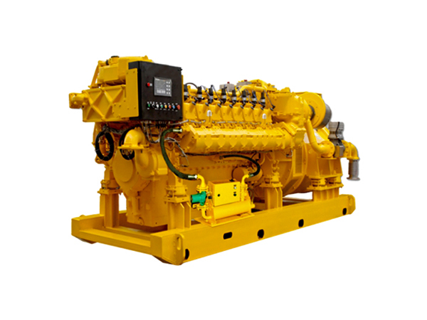
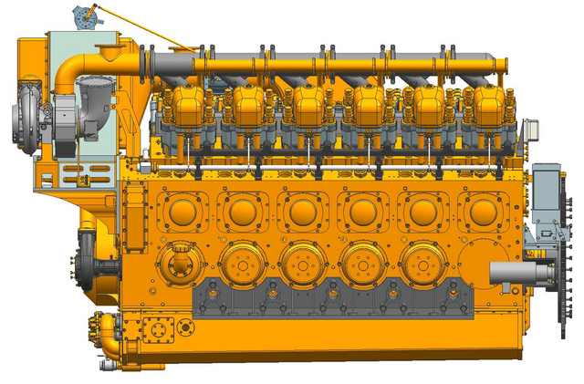
A generator room may have large vents and still run too hot. Undersized openings, restrictive louvers, poor airflow direction, or recirculated radiator discharge can limit combustion air and push equipment beyond its intended operating temperature. Exhaust leakage adds a separate risk because carbon monoxide is colorless, odorless, and hazardous in enclosed spaces.
Effective ventilation begins with the selected Natural Gas Generator Set, site temperature, cooling arrangement, room layout, and pressure losses. The checklist below helps buyers and project teams size openings, position inlets and outlets, separate exhaust safely, and verify performance under load.
Confirm the Design Inputs Before Planning Any Openings
Collect the Generator’s Technical Data
Ventilation planning should begin with the generator technical submittal, not with a contractor selecting louvers from a catalogue. Required information includes combustion-air demand, radiator airflow, heat rejection to the room, maximum intake-air temperature, allowable external static pressure, exhaust flow, and exhaust backpressure limits. Dimensions, radiator position, air-cleaner location, access doors, and component-removal space are equally relevant because they determine how air can move around the equipment.
Record the Actual Site Conditions
The design basis should reflect the hottest expected operating day rather than an annual average temperature. Altitude, humidity, dust, salt exposure, prevailing wind, and whether the room is below grade or partly enclosed can all change system performance. The calculation must also cover every Natural Gas Generator Set that may operate simultaneously.
Nearby doors, windows, courtyards, roof overhangs, and building air intakes should be shown on the site plan. Noise requirements must be recorded early because acoustic louvers and attenuators add resistance. Future expansion also matters; adding another unit later may overwhelm openings designed for only one generator.
Design Input
How It Affects Ventilation
Where to Obtain It
Radiator airflow
Establishes the principal discharge-air volume
Generator technical data
Heat rejection to room
Determines additional heat-removal demand
Engine and alternator data
Static-pressure limit
Restricts acceptable duct and louver resistance
Manufacturer documentation
Maximum site temperature
Defines the worst cooling condition
Project weather data
Simultaneous operation
Determines the total room airflow requirement
Facility operating plan
Size Airflow, Louvers, and Fans Without Relying on Shortcuts
Separate Combustion Air from Cooling Air
Several airflow demands exist inside a generator room, and they should be identified separately before the final quantity is selected. The engine consumes air during combustion, while an engine-mounted radiator moves a much larger volume across the cooling core. Additional room ventilation removes heat released from the engine block, alternator, exhaust piping, silencer, electrical equipment, and auxiliary systems.
These requirements may overlap, but they are not automatically interchangeable. Radiator airflow can contribute to room cooling only when replacement air reaches the equipment and the heated discharge leaves without recirculating. A remote-radiator or heat-exchanger installation creates a different heat balance because less cooling air may pass through the generator room.
Calculate Heat-Removal Airflow for the Worst Operating Condition
Start by adding the heat released into the room by all equipment expected to operate together. Select an allowable difference between outdoor intake temperature and the maximum acceptable indoor temperature, then determine how much air is needed to carry that heat away. For an industrial Natural Gas Generator Set, the calculation should use full-load or maximum expected conditions rather than a lightly loaded test value.
High ambient temperature leaves less temperature difference available for heat removal, which generally increases the required airflow. Altitude can also affect air density and engine performance, while long ducts and restrictive louvers reduce the volume that actually reaches the room. The completed calculation must be checked against the engine’s permissible intake restriction and the radiator’s allowable external static pressure.
A fixed CFM-per-kW figure is useful only as a preliminary sense check. It does not account for whether the set has an engine-mounted radiator, remote cooling, unusually high exhaust heat, multiple operating units, or a hot installation climate. Selecting openings from a universal ratio can therefore produce a system that appears generous on paper but fails at full load.
Convert Airflow into Net Free Opening Area
A louver’s outside width and height do not equal its usable airflow area. Blades, frames, screens, filters, weather hoods, dampers, and acoustic elements reduce the net free area and create pressure loss. Designers should therefore select components from published performance data at the required airflow, not from nominal dimensions.
Duct resistance must include straight lengths, transitions, bends, grilles, silencers, and protective screens. Abrupt reductions or tight elbows near a radiator can be particularly restrictive. The sum of these losses should remain within the limits supplied for the water-cooled Natural Gas Generator Set.
Installing a stronger exhaust fan is not a reliable correction for an undersized inlet. Excessive negative pressure may reduce combustion-air availability, make doors difficult to open, and pull conditioned or contaminated air from adjacent spaces. Where dampers control combustion-air openings, the operating sequence should prevent the generator from running against a closed damper.
Make the Air Travel Through the Room, Not Around It
Position the Inlet and Outlet Around the Generator
The air inlet should be positioned so cooler outdoor air passes across the equipment before reaching the hot-air discharge. In a typical arrangement, air enters near the alternator or engine-intake end, moves over the controls and engine, crosses the radiator, and exits directly outdoors. This path removes heat instead of allowing incoming air to bypass the generator through the shortest route between two wall openings.
Inlets and outlets placed too close together can ventilate only one part of the room. Corners behind switchgear, battery racks, wall-mounted controls, and auxiliary skids may remain significantly hotter than the measured temperature near the door. Several temperature points should therefore be considered when evaluating the design.
Maintenance access must remain part of the layout. Large ducts should not block filter removal, valve access, radiator cleaning, or major engine work. A technically adequate airflow arrangement can still become impractical when routine service requires dismantling the ventilation system.
Stop Hot Air from Returning to the Inlet
Radiator discharge should be connected to the outdoor opening through a properly sized and sealed transition. Gaps around the connection allow heated air to spill back into the room, where it is drawn through the radiator again. Each recirculation cycle raises the cooling-air temperature and reduces the radiator’s ability to reject heat.
The external arrangement needs the same attention. Wind can force hot discharge back toward an inlet, while nearby walls, screens, roof canopies, and enclosed yards can trap a plume beside the building. Discharge openings should also be separated from windows, doors, occupied areas, and HVAC intakes.
Rooms containing more than one high-output Natural Gas Generator Set require an operating-scenario review. One generator must not discharge toward the intake of another unit, particularly when units are installed in a line or opposite each other. Outdoor airflow should be evaluated with every planned combination of generators running.
A clear design path can be represented as:
Outdoor air inlet → alternator and controls → engine → radiator → sealed outdoor discharge
Treat Exhaust and Gas-Leak Protection as Separate Safety Systems
Route Engine Exhaust Directly Outdoors
Normal engine exhaust should never be released into the room for ventilation fans to dilute. Combustion products must travel through a gas-tight exhaust system to an approved outdoor location. Flexible connections accommodate engine vibration, while independently supported piping prevents the exhaust manifold from carrying the weight of long pipes or silencers.
The route should allow thermal expansion, condensate drainage, and inspection of joints. Hot surfaces need insulation or guarding where personnel may make contact, but the selected insulation should not conceal leakage or corrosion indefinitely. Unnecessary bends and excessive pipe length should be avoided because the complete system must remain within the engine’s backpressure limit.
Termination location is as important as pipe construction. Exhaust should not be directed toward ventilation inlets, windows, doors, walkways, roof work areas, or neighbouring buildings. Carbon monoxide is colorless and odorless and can accumulate rapidly in enclosed or apparently ventilated spaces, so smell cannot be used as a warning method.
Plan for Natural Gas Leakage
The room safety review should identify regulators, valve trains, flexible connections, flanges, joints, meters, and shutoff valves as possible leakage locations. Detector placement must reflect the room geometry, ceiling features, airflow direction, equipment instructions, and applicable code rather than being selected solely for convenient wiring. Fans should not carry a released gas cloud toward occupied areas or other ignition sources.
Define the Alarm and Shutdown Sequence
The project team should prepare a cause-and-effect schedule for high room temperature, fan failure, low airflow, closed dampers, abnormal room pressure, combustible gas, and carbon monoxide. Each condition should have a defined response, such as a local warning, remote annunciation, standby fan start, fuel isolation, controlled shutdown, or emergency stop. The sequence must distinguish between conditions that allow an orderly cooldown and those requiring immediate isolation.
Automatic ventilation components should reach their operating positions before the Natural Gas Generator Set accepts load. Status should be proven through switches, airflow sensors, pressure devices, or other suitable feedback rather than assumed from a start command. A running fan motor does not confirm that a belt is intact, a damper is open, or an outdoor screen is clear.
Prove the Ventilation Works Under Load
Complete a Full-Load Commissioning Check
Commissioning should demonstrate performance with the room in its normal operating configuration. Doors should be closed, access panels installed, filters fitted, and acoustic components in place. Fans, louvers, dampers, alarms, and generator controls should then be operated through the intended automatic sequence.
Run the Natural Gas Generator Set at the highest practical load until temperatures stabilize. Record outdoor temperature, electrical load, room temperature at several positions, engine-intake temperature, radiator inlet temperature, airflow, and room pressure relative to adjacent spaces. Results from a cool morning or short unloaded run should not be treated as proof of hot-weather capacity.
Alarm and interlock tests are part of commissioning rather than optional demonstrations. Simulate fan failure, loss of airflow, high temperature, and detector inputs where this can be done safely under the approved procedure. After correcting a failed result, repeat the relevant operating test and document the new measurements.
Keep the Air Path Clear During Operation
Ventilation performance deteriorates gradually when radiator fins, screens, filters, or louvers collect dust and debris. Fan belts loosen, damper actuators stick, duct seals separate, and stored materials migrate toward air openings. Maintenance should therefore examine the full airflow path rather than only servicing the engine.
Use the following readiness checklist during scheduled inspections and after room modifications:
● Generator airflow and heat-rejection data remain available and current.
● Air inlets, louvers, screens, filters, and radiator surfaces are clean.
● Radiator transitions and flexible duct connections remain sealed.
● Exhaust joints, insulation, supports, and condensate drains are serviceable.
● Gas detectors, CO detectors, alarms, fuel isolation, and shutdown controls pass functional tests.
● No storage, partitions, acoustic materials, or new equipment obstruct the designed air path.
● Full-load results and corrective actions are retained in the maintenance record.
Conclusion
A reliable generator room depends on more than installing large vents or powerful fans. Airflow must match the generator’s heat rejection and combustion demand, while inlet placement, pressure loss, exhaust routing, gas detection, and full-load testing all require careful coordination. These checks help prevent overheating, recirculation, unsafe gas accumulation, and avoidable performance loss.
Jiangsu Kelinyuan Clean Energy Technology Co., Ltd. supplies Natural Gas Generator Set solutions with technical support for model selection, system configuration, installation, and commissioning, helping project teams align generator performance with actual room and site conditions.
FAQ
Q: How much ventilation does a generator room need?
A: Required airflow depends on combustion demand, heat rejection, ambient temperature, allowable room-temperature rise, radiator airflow, and pressure losses through louvers, screens, ducts, and silencers.
Q: Where should generator-room air inlets and outlets be placed?
A: Introduce cooler air near the engine-intake side and discharge heated radiator air outdoors. Keep both openings separated to prevent short-circuiting and hot-air recirculation.
Q: Can room ventilation replace the engine exhaust pipe?
A: No. Combustion gases must leave through a sealed exhaust system. General ventilation controls room heat and replacement air but cannot safely manage normal carbon monoxide emissions.
Q: What causes a Natural Gas Generator Set room to overheat?
A: Common causes include undersized openings, blocked louvers, dirty radiator cores, restrictive ductwork, failed fans, poor airflow direction, and heated discharge air returning to the inlet.
Q: Does a natural gas generator room need gas and carbon monoxide detectors?
A: Detector requirements depend on local codes and the project risk assessment. Natural gas and carbon monoxide require separate detection because one sensor does not necessarily monitor both hazards.