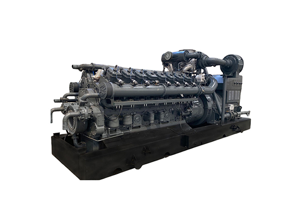
Modern oil and gas operators face intense pressure to eliminate routine flaring while managing the escalating logistical burdens of remote site power. Converting raw, untreated flare gas into reliable electricity requires overcoming severe technical hurdles. You deal with wildly fluctuating gas volumes, inconsistent BTU values, and harsh environmental conditions. Standard equipment fails rapidly in these applications. You need a rigorously specified oil field gas generator set engineered specifically for these variables. This guide provides a technical framework for evaluating equipment and mitigating deployment risks. We cover engine matching, contaminant tolerance, and upstream system integration. You will learn how to transition from wasteful flaring to reliable on-site power generation, ensuring emissions compliance and operational autonomy without compromising site safety.
Gas Composition Dictates Equipment: Raw associated gas requires precise engine matching and pre-treatment; failure to account for H2S and moisture leads to premature engine failure.
Sizing for Variability is Critical: Flare gas flow rates fluctuate. Selecting a generator with high turndown capabilities or modular configurations prevents underloading and wet stacking.
Efficiency Multipliers (WHR): Integrating Waste Heat Recovery (WHR) can drastically increase the overall efficiency of the system by repurposing exhaust heat for site operations.
Vendor Expertise Mitigates Risk: Partnering with a specialized gas generator set manufacturer ensures proper Factory Acceptance Testing (FAT) and site-specific commissioning, reducing costly downtime.
The Strategic Role of an Oil Field Gas Generator Set in Flare Gas Recovery
Deploying a generator for flare gas recovery requires defining strict success criteria based on field realities. You must achieve measurable emissions compliance. This means significantly reducing methane slip and lowering the overall carbon footprint of the well pad. You also need high operational uptime and complete power autonomy. A successful deployment transforms a problematic waste stream into a core operational asset that drives site production.
Shifting from flaring to associated gas power generation involves a major mechanical and infrastructure transition. You stop burning waste gas openly in a flare stack. Instead, you route this gas through a prime-mover engine. This engine generates electricity to run critical site operations. You can power pump jacks, gas compressor stations, fluid transfer pumps, or entire remote microgrids. This transition directly offsets the logistical nightmare of scheduling continuous diesel fuel deliveries to isolated locations.
Implementing a flare gas recovery system aligns directly with corporate Environmental, Social, and Governance (ESG) targets. The global market for flare gas recovery is expanding rapidly as regulations tighten. Operators who adopt this technology future-proof their operations against stricter environmental mandates. You position your company as a responsible energy producer while solving a fundamental site power deficit.
Regulatory frameworks are tightening globally across all major shale plays and offshore platforms. Initiatives like the World Bank's Zero Routine Flaring by 2030 mandate force operators to find immediate alternatives to flaring. Deploying the right generator set helps you meet these local and international mandates. You avoid heavy regulatory fines, prevent forced production curtailments, and maintain your social license to operate. Compliance becomes a natural byproduct of efficient power generation.
Core Technical Evaluation Criteria for Oil Field Power Solutions
Gas Composition and Contaminant Tolerance
Raw associated gas is highly variable and heavily contaminated. You must evaluate the Methane Number (MN) and Lower Heating Value (LHV) of your specific gas stream before selecting an engine. A low Methane Number indicates a high concentration of heavier hydrocarbons like ethane, propane, and butane. This drastically increases the risk of engine knock or pre-ignition. Engines operating on low MN gas often require significant power derating or lower compression ratios to prevent catastrophic piston failure. The LHV determines the physical volume of gas needed to achieve your target electrical output.
Your oil field power solution must tolerate severe contaminants without excessive downtime. Hydrogen Sulfide (H2S) is highly corrosive and prevalent in sour gas fields. When H2S combusts and mixes with water vapor in the exhaust, it forms sulfuric acid. This acid rapidly degrades engine oil, attacks yellow metal bearings, and destroys exhaust manifolds. Siloxanes present another major mechanical threat. During combustion, siloxanes turn into silicon dioxide, which is essentially microscopic sand. This abrasive material coats cylinder walls, fouls spark plugs, and destroys piston rings.
Heavy hydrocarbons, or Natural Gas Liquids (NGLs), cause erratic combustion and carbon buildup. You must specify engines built with hardened internal components. Look for stellite-faced valves, hardened valve seats, specialized piston ring packs, and heavy-duty connecting rods. These upgrades are mandatory for surviving corrosive associated gas environments. Standard natural gas engines designed for pipeline-quality fuel will fail within weeks under these harsh field conditions.
Contaminant / Variable
Impact on Standard Engines
Required Engine Modification
Low Methane Number (< 50)
Severe knocking, pre-ignition, piston melting
Lower compression ratio pistons, retarded ignition timing, power derating
You must choose between rich-burn and lean-burn engine technologies based on your site load profile. Rich-burn engines operate near a stoichiometric air-to-fuel ratio (Lambda ~1.0). They offer excellent transient load response. This makes them ideal for starting large electric motors, such as those on pump jacks or gas compressors, which draw massive inrush currents. They also allow for easier emissions compliance. You can use standard 3-way non-selective catalytic reduction (NSCR) to eliminate NOx, CO, and unburned hydrocarbons. However, rich-burn engines consume more fuel and run at higher exhaust temperatures.
Lean-burn engines operate with a significant excess of air (Lambda 1.6 to 2.0). This excess air lowers peak combustion temperatures inside the cylinder. Lower temperatures drastically reduce raw NOx emissions before the exhaust even leaves the engine. Lean-burn engines offer much higher fuel efficiency and mechanical output. They are excellent for steady, continuous baseload power applications. However, they struggle with sudden load spikes and require more complex exhaust aftertreatment, like Selective Catalytic Reduction (SCR) systems with urea injection, to meet ultra-low emissions targets.
Evaluation Feature
Rich-Burn Engines
Lean-Burn Engines
Air/Fuel Ratio (Lambda)
Stoichiometric (~1.0)
Excess Air (1.6 - 2.0)
Transient Load Response
Excellent (Handles sudden motor starts)
Moderate (Best for steady baseloads)
Fuel Efficiency
Lower
Higher
Raw NOx Emissions
High (Requires 3-way catalyst)
Low (In-cylinder reduction)
Ideal Field Application
Off-grid pump jacks, varying cyclic loads
Grid-tied, continuous steady power generation
Waste Heat Recovery (WHR) and Cogeneration (CHP)
Generating electricity captures only about 35% to 40% of the energy available in flare gas. You must evaluate Waste Heat to Power (WHP) or Combined Heat and Power (CHP) capabilities to maximize site efficiency. Internal combustion engines reject massive amounts of thermal energy through the exhaust stack and the jacket water cooling systems. Capturing this thermal energy acts as a massive efficiency multiplier for your entire well pad.
You can redirect captured exhaust heat, which often exceeds 900°F, to warm oil treaters and maintain flowline temperatures in cold climates. You can use jacket water heat, typically around 200°F, to separate heavy crude emulsions in settling tanks. In advanced setups, you can route high-grade exhaust heat through a secondary Organic Rankine Cycle (ORC) turbine. This turbine generates additional electricity without consuming any extra fuel. Maximizing the utility of captured flare gas improves your overall site energy balance and reduces the need for secondary gas-fired heaters.
Load Step Capabilities and Island Mode Operation
Remote oil fields often operate entirely off-grid. This is known as island mode operation. In island mode, your generator is the sole source of power, and the grid cannot stabilize your frequency. Transient response becomes the most critical performance metric. You must evaluate how the generator handles sudden, massive load spikes. Starting a large electric submersible pump (ESP) or a variable frequency drive (VFD) compressor draws a massive inrush current, often three to six times the motor's running current.
If the generator cannot respond quickly to this demand, the voltage and frequency will drop severely. This causes sensitive site equipment to trip offline. In worst-case scenarios, the engine stalls completely, causing a total site blackout. You must review the manufacturer's load step acceptance curves against ISO 8528-5 standards. Ensure the alternator is oversized appropriately to handle high starting kVA (skVA) requirements without allowing voltage dips to exceed 15%.
Sizing and Integrating a Flare Gas Recovery System
Handling Flow Rate Variability and Turndown Ratios
Oil wells do not produce associated gas at a constant rate. Well curves decline predictably over time, and flare volumes fluctuate daily based on process conditions and separator pressures. You must size your equipment to handle this inherent variability. Purchasing one massive generator based on initial peak flow is a common engineering mistake. If gas volumes drop, a large engine will run at a low load. This causes wet stacking, where unburned fuel and lubricating oil accumulate in the exhaust system, leading to fires and engine damage.
Evaluate the operational advantages of modular configurations. Deploying multiple smaller units offers immense flexibility. You can bring individual engines online or offline to perfectly match the available gas volume at any given hour. Define acceptable turndown ratios with your vendor. A high turndown ratio allows the engine to run safely at lower loads (e.g., 40% of rated capacity) without glazing the cylinder liners or fouling the spark plugs.
Pre-Treatment, Flare Header Integration, and Safety
The generator is only one component of a complete recovery system. Upstream gas conditioning is absolutely mandatory to protect the engine and ensure safe operation. You must integrate specific equipment to handle the raw gas before it reaches the fuel train.
Liquid Ring Compressors: Install these to create a safe, controlled suction on the flare header, pulling the gas toward the generator without disrupting separator pressures.
Knockout Drums: Deploy these vessels to separate entrained free liquids, water, and heavy mist from the gas stream.
Gas Chillers: Use refrigeration units to drop the gas temperature, forcing heavy natural gas liquids (NGLs) to condense and drop out of the stream.
H2S Scrubbers: Route sour gas through chemical or biological scrubber beds to remove hydrogen sulfide, sweetening the gas to acceptable engine limits.
Safety is the ultimate imperative during integration. You must maintain precise pressure control on the flare header. If the compressor pulls a vacuum on the pipe, it will draw ambient oxygen into the system. Oxygen mixed with hydrocarbon gas creates an immediate, catastrophic explosion hazard. You must use fast-acting PID controllers to manage bypass valves and maintain positive pressure.
You must maintain active flare ignition and pilots at all times. If the generator trips offline due to a fault, the gas must instantly bypass back to the flare stack to prevent plant overpressure. Evaluate packaged solutions carefully. A skid-mounted system that combines the generator, gas conditioning, and safety controls is generally safer and easier to deploy than piecemeal integration managed by multiple contractors.
Microgrid Deployment and Grid Synchronization
Many modern oil fields operate as complex microgrids, integrating multiple power sources. You must outline the technical requirements for synchronizing your gas generator with existing site power. In a hybrid setup, you might parallel the gas generator with existing diesel generators or battery energy storage systems (BESS). The gas unit takes the steady baseload, while the diesel units handle transient spikes or act as emergency backup.
If you operate near utility lines, you might export surplus power back to the local grid. This transforms an industrial gas power plant into a revenue-generating asset. You need advanced switchgear to manage this complex routing. Paralleling controllers handle isochronous load sharing, automatic synchronization, dead bus closing, and seamless grid decoupling during utility outages to protect linemen.
Vetting a Gas Generator Set Manufacturer: Risk Mitigation
Supply Chain and Spare Parts Availability
A generator is useless if it sits broken waiting for parts. Poor aftermarket support creates stranded assets and forces you back to flaring. You must rigorously vet your gas generator set manufacturer. Ask hard questions about localized parts inventory. Do they stock critical spares in your specific geographic region? Relying on overseas shipping for a replacement cylinder head, turbocharger, or specialized actuator will cost you weeks of downtime and lost production.
Evaluate their technician dispatch times. You need guaranteed response windows written into your contracts. Assess their supply chain redundancies. A reputable manufacturer maintains multiple sourcing channels for high-wear items like spark plugs, air filters, oil filters, and specialized high-TBN lubricants. Do not commit to a vendor who cannot prove their localized support capabilities with physical warehouse locations near your field operations.
Factory Acceptance Testing (FAT) and Site Commissioning
Never accept delivery of a generator without rigorous Factory Acceptance Testing (FAT). The FAT must simulate your actual site conditions as closely as possible. Demand that the manufacturer uses simulated gas blends during the test to match your expected Methane Number. Running the engine on clean, pipeline-quality natural gas during FAT proves nothing if your site produces heavy, sour associated gas.
Site commissioning requires equal engineering rigor. The vendor must perform comprehensive load bank testing on location. This proves the cooling system can handle your specific ambient temperatures while under full load. Commissioning must also include complete integration with your site's SCADA system. You need full remote visibility into engine parameters, fault codes, exhaust temperatures, and power output from your central control room.
Service Level Agreements (SLAs) and Remote Monitoring
Modern generators generate massive amounts of telemetry data. Evaluate the importance of OEM-provided remote monitoring and telematics. Continuous monitoring of exhaust temperatures, oil pressure, vibration signatures, and coolant flow allows for predictive maintenance. You can identify and replace a failing component before it destroys the engine block.
Structure your Service Level Agreements (SLAs) to guarantee mechanical uptime. Hold the manufacturer accountable for performance metrics. If the unit fails to meet the agreed-upon availability percentage, the SLA should dictate mandatory replacement clauses or expedited service requirements. A strong SLA shifts operational risk back to the vendor and ensures they remain invested in the success of your deployment.
Conclusion
Take these concrete steps to initiate your flare gas recovery project:
Execute a comprehensive gas analysis using gas chromatography to determine your exact Methane Number, LHV, and H2S concentrations.
Audit your site load profile to capture peak starting kVA requirements and steady-state baseloads for accurate alternator sizing.
Specify modular generator configurations to ensure you can maintain optimal engine loading as wellhead production curves decline over time.
Demand localized spare parts guarantees and rigorous Factory Acceptance Testing protocols before signing any procurement contracts.
FAQ
Q: What is the difference between a standard natural gas generator and an oil field gas generator set?
A: Standard generators require clean, dry, pipeline-quality gas. Oil field units feature modified fuel trains, lower compression ratios, and hardened internal components. They use stellite-faced valves and specialized bearings to withstand corrosive H2S, abrasive siloxanes, and heavy natural gas liquids found in raw associated gas.
Q: How does a flare gas recovery system integrate with the existing flare stack?
A: The system uses liquid ring compressors or blowers to pull a controlled suction from the flare header upstream of the stack. Crucially, the flare pilot light remains active. Fast-acting bypass valves ensure that if the generator trips, gas immediately routes back to the flare to prevent dangerous plant overpressure.
Q: How much flare gas is required to generate 1 MW of power?
A: As a general rule of thumb, generating 1 MW of continuous power requires approximately 250 to 300 thousand cubic feet per day (Mcf/d) of associated gas. However, the exact volume depends heavily on the Lower Heating Value (LHV) of your specific gas stream and the mechanical efficiency of the engine.
Q: Can a flare gas recovery system completely eliminate routine flaring?
A: Yes, it can eliminate routine, daily flaring by consuming the baseline gas volume for power generation. However, emergency flaring capabilities must always remain intact. The flare stack acts as a critical safety relief valve during plant trips, compressor failures, or scheduled generator maintenance downtime.
Q: What pre-treatment is necessary for associated gas power generation?
A: Raw gas requires extensive conditioning before entering the engine. Standard pre-treatment includes knockout pots for bulk liquid and moisture removal, gas chillers to drop out heavy hydrocarbons, pressure regulation valves, and H2S scrubbing systems to sweeten sour gas and prevent severe engine corrosion.
Q: How do ambient temperatures affect generator performance in the oil field?
A: High ambient temperatures reduce air density, which limits the mass of oxygen entering the cylinders, causing power derating. Extreme heat also strains the jacket water cooling system. Generators deployed in hot climates require oversized radiators and specialized cooling loops to maintain full power output without overheating.