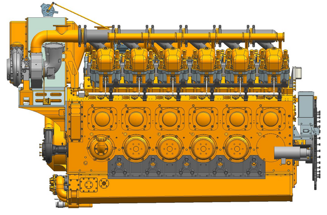
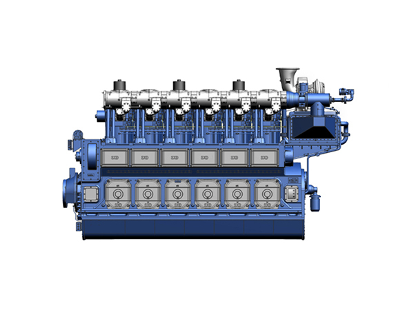
A Gas Generator Set that starts cleanly on the factory floor can still fail once real load is applied. Gas pressure may drop, combustion may become unstable, temperatures can rise too quickly, or voltage and frequency may recover too slowly after a sudden demand change. These are the problems pre-delivery testing is meant to expose.
A well-planned Factory Acceptance Test helps buyers verify performance before shipment, when corrections are still easier to make. The following sections explain how to define acceptance criteria, inspect the unit, test it under representative gas and load conditions, and review protection functions and records.
Set the Pass-or-Fail Rules Before the Test Starts
Turn the purchase specification into measurable test points
A useful FAT procedure begins with the approved technical specification, not a generic checklist copied from another project. The buyer and manufacturer should first confirm the intended duty rating, rated kW and kVA, voltage, frequency, phase arrangement, power factor, gas composition, inlet pressure, cooling method, starting system, ambient conditions, and emissions requirements. Every contractual value must be translated into a test point with a defined measurement and an acceptable result.
Agree on tolerances, witnesses, and retest conditions
The test plan should identify who conducts the FAT, who witnesses it, and who has authority to accept or reject the results. Measuring instruments need valid calibration records, while the procedure should state sampling intervals, stabilization periods, load stages, temperature limits, pressure limits, and permissible voltage and frequency variation. Corrective-action rules must also explain which defects require an immediate stop and when a complete retest is necessary.
Inspect the Finished Unit Before the First Start
Confirm that the delivered build matches the approved order
Before fuel is introduced or the starter is engaged, the completed generator should be compared with the purchase order, approved drawings, technical agreement, and bill of materials. Inspectors should verify the engine, alternator, controller, nameplates, skid dimensions, vibration mounts, coupling, guards, lifting points, terminal box, grounding connections, cable entries, sensors, heaters, chargers, and ordered accessories. Serial numbers and nameplate ratings should be photographed so the final report clearly identifies the tested machine.
Visual inspection must go beyond cosmetic appearance. Loose fasteners, damaged wiring, incorrect cable markings, misaligned components, missing guards, or substituted accessories can affect safe operation even when the unit looks complete. Cosmetic paint damage may remain on a minor punch list, but any discrepancy involving safety, performance, or contractual scope should be resolved before the first start.
Check the gas, lubrication, cooling, and starting systems
The gas train requires a documented leak test covering filters, regulators, shutoff valves, flexible connections, pressure switches, vents, and related piping. Test fuel should represent the project gas closely enough to reveal combustion or pressure-regulation problems. Where composition differs materially, the manufacturer should document the assumed heating value and explain how the results are corrected or interpreted.
Lubricating oil and coolant must match the approved grade, concentration, and fill level. Pre-lubrication should establish oil circulation before cranking, while pumps, thermostats, fans, heat exchangers, and both cooling circuits must be prepared for operation. Intake and exhaust paths also need inspection for shipping covers, temporary blanks, loose joints, restrictions, or excessive back-pressure risk.
Establish the electrical condition before energization
Alternator insulation resistance and phase winding balance should be measured using the manufacturer’s approved procedure before the output terminals are energized. Inspectors should also examine terminal torque, grounding continuity, phase identification, excitation components, control wiring, and separation between power and signal circuits. Ambient temperature and humidity must be recorded because environmental conditions influence the interpretation of insulation readings.
Pre-Start Checklist
●Model, ratings, configuration, and serial numbers match the approved order.
●The gas train has passed its leak and pressure checks.
●Lubrication, coolant, pre-lubrication, and starting systems are ready.
●Cooling, ventilation, intake, and exhaust paths are unobstructed.
●Alternator insulation, grounding, terminals, and control wiring have been checked.
●No unresolved safety-critical or performance-related defects remain.
Prove Performance with Representative Gas and Controlled Loads
Repeat the start sequence and observe stabilization
One successful start is not enough to prove reliable starting performance. The FAT should include repeated cold or stabilized starts, normal stops, hot restarts, and start-failure simulations where practical. During each sequence, technicians should record cranking or starting-air duration, ignition time, oil-pressure buildup, engine speed, voltage, frequency, battery voltage or air pressure, and active controller messages.
The engine should reach stable speed and electrical output without prolonged hunting, abnormal vibration, unusual mechanical noise, persistent smoke, leakage, or fault codes. A short no-load run can confirm basic function, but extended idling provides little evidence about usable generating capacity. Once initial checks are complete, the test should move promptly to controlled loading.
Check combustion as gas pressure and load change
Gas pressure must be measured upstream and downstream of the regulating equipment throughout the load test. A supply that appears adequate at idle may fall below the required range when fuel demand rises. Pressure collapse, regulator hunting, unstable valve response, or inadequate piping capacity can produce derating, misfire, knock, and poor transient recovery.
Combustion data should be viewed as a connected system rather than a collection of isolated readings. Air-fuel ratio, ignition timing, cylinder balance, exhaust-temperature spread, gas consumption, engine speed, knock signals, and emissions all help show whether combustion remains stable. A large difference between cylinder exhaust temperatures, for example, may point to uneven fuel delivery or ignition performance even when total output appears acceptable.
Hold each load stage long enough to reveal developing faults
A calibrated load bank should apply progressive stages from low load through medium and high load to the agreed rated output. The exact percentages and holding periods belong in the approved FAT procedure because generator size, duty, cooling arrangement, and project requirements differ. Each stage should last long enough for operating values to settle before the next increase.
Recorded data should include kW, kVA, voltage on each phase, current, frequency, power factor, engine speed, gas pressure, fuel consumption, oil pressure, oil temperature, coolant inlet and outlet temperatures, intake temperature, exhaust temperature, winding or bearing temperature, and ambient conditions. Where emissions form part of the contract, NOx, CO, oxygen, and other specified values should be taken only after combustion has stabilized. Readings should be time-stamped so the buyer can see trends instead of receiving only a final average. For a large-capacity gas generator set, the FAT should also include reactive loading whenever the purchased configuration is rated for a lagging power factor.
The highest approved load requires enough operating time for thermal stabilization. Many faults develop gradually: coolant temperature may continue climbing, gas pressure may decline, exhaust back pressure may become excessive, or alternator temperatures may fail to level off. A brief full-load peak can therefore create an unrealistically favorable result.
Test sudden load changes, not just steady output
Steady-state output proves that thenatural gas generator set can carry a controlled load once stabilized. It does not show how the machine will respond when a large motor, compressor, pump, transformer, or process line is connected suddenly. Step-load tests should therefore reflect the largest credible block load in the buyer’s application rather than use an arbitrary percentage with no link to site demand.
During load application, the test team should capture voltage dip, frequency dip, minimum engine speed, recovery time, speed oscillation, combustion stability, governor response, and voltage-regulator behavior. Excessive deviation may cause connected equipment to trip even though the generator eventually returns to nominal output. Slow recovery can also reveal inadequate engine reserve, poor tuning, or an unrealistic load-acceptance expectation.
Load rejection creates a different challenge. Removing a substantial block suddenly can cause overspeed, overvoltage, hunting, unstable air-fuel control, or delayed return to steady conditions. Both application and rejection tests are needed because one examines the ability to supply additional energy, while the other examines how safely the controls reduce it.
Parallel-ready equipment requires further checks when synchronization and load sharing form part of the supplied scope. These may include phase matching, breaker interlocks, active and reactive load sharing, reverse-power protection, and response when one unit joins or leaves the bus. Site switchgear will still require commissioning, but factory tests can verify the generator-side functions before shipment.
Challenge the Protection System and Review the Evidence
Simulate every relevant alarm and shutdown
Protection testing should prove actual controller response rather than confirm that an alarm name appears in a menu. Depending on the supplied configuration, simulations may cover emergency stop, low oil pressure, high coolant temperature, overspeed, overcrank, high or low gas pressure, gas leakage, knock, misfire, cooling failure, overvoltage, undervoltage, overfrequency, underfrequency, overcurrent, reverse power, and earth fault.
Each test needs a defined initiating condition and expected outcome. The witness should confirm the displayed alarm wording, audible or visual indication, warning or shutdown action, event timestamp, remote output, reset sequence, and restart permission. A sensor value appearing on the controller does not prove that the related trip will operate at the correct point.
Temporary overrides used during simulation must be logged and removed afterward. The closing run should confirm that sensors, shutdowns, communication outputs, and protection settings have returned to their approved operating state.
Release the generator only after the record is complete
Following the performance tests, the team should conduct a hot inspection for leaks, loose connections, abnormal odor, discoloration, damaged insulation, or localized overheating. All safety- and performance-related nonconformities must be closed before shipment. If repairs affect combustion, cooling, output, wiring, controls, or protection settings, the relevant test should be repeated rather than accepted through a visual check alone.
The final package should include the signed FAT procedure, raw operating data, load-bank records, transient-response graphs, alarm and shutdown test sheets, gas data, emissions results where required, calibration certificates, controller settings, protection set points, serial numbers, corrective-action records, drawings, manuals, photographs, and witnessed video where applicable. Preservation, lifting, packing, and shipping instructions should also match the tested configuration.
A polished summary stating that the gas generator set “passed” is not sufficient without the underlying readings and signatures. Traceable records allow the buyer to compare factory results with receiving inspection and site commissioning, while also establishing accountability for any discrepancy discovered after delivery.
Conclusion
Reliable pre-delivery testing should confirm more than a successful start. A Gas Generator Set must prove stable combustion, rated output, acceptable thermal behavior, responsive load recovery, correct protection logic, and complete test records before shipment is approved. Jiangsu Kelinyuan Clean Energy Technology Co., Ltd. supports this process through generator design, manufacturing, testing, commissioning, and technical service tailored to fuel type and site conditions. By matching equipment configuration and acceptance criteria to the real project, buyers can reduce commissioning delays, identify defects earlier, and receive a system better prepared for dependable operation.
FAQ
Q: What should be included in pre-delivery testing for a Gas Generator Set?
A: Testing should cover visual inspection, gas-train leak checks, starting performance, staged loading, voltage and frequency stability, thermal behavior, transient response, alarms, shutdowns, and final records.
Q: Why is load bank testing necessary before delivery?
A: A load bank applies controlled electrical demand, showing whether the generator can sustain rated output and maintain acceptable temperature, voltage, frequency, and recovery performance.
Q: How long should a factory generator load test run?
A: There is no universal duration. The FAT should define load stages and holding times based on the rating, application, cooling system, and agreed acceptance criteria.
Q: What is the difference between FAT and SAT for a generator?
A: A Factory Acceptance Test is completed before shipment under controlled factory conditions. A Site Acceptance Test follows installation and verifies performance with actual site connections, fuel, and loads.
Q: What documents should buyers receive after generator testing?
A: The report should include raw readings, load steps, gas pressure, temperatures, electrical output, transient results, alarm tests, calibration records, defects, corrective actions, and signed acceptance.